Douglas A/B-26 Invader
The restoration
Douglas A/B-26 Invader The restoration |
|||||
|
Carl
Sgamboti, (Crew Chief) Bob
Grzech, K.B. Snow (USAF, Ret.)
John
Smith, (USN, Ret.) Bill
Stevens (USAF, Ret.) John
O’Connor, (USAF, Ret.) Pete
McConnell Dave
Leonard Art
Richards Fran
Lambour Machine Shop:
Brian Bailey, Stu Bailey, Paul Mangiafico, Engine Restoration: Don Kiley, Jim Godin, Connie Lachendro, Monsignor Douglas Clancy, Fred Tieman, Mel McGowan Metal Working:
Tom Palshaw, Bob Jackson, Harry Newman, Ralph Redman
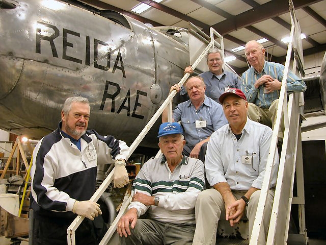
1st Row: Bob Grzech, K.B. Snow (USAF, Ret.), Carl Sgamboti,
(Crew Chief) 2nd Row: John Smith, (USN, Ret.) 3rd Row: Bill
Stevens (USAF, Ret.), John O’Connor, (USAF, Ret.)
Six Gun Nose Ammo box and gun mounting area Tail Work Polishing horizontal stabilizer Reida Rae tail code applied after 50 years! Nacelle and Fuel Tank Well Repair Flap Motor refurbishment Flap motor in place on rear bomb bay bulkhead Pilot Cockpit Hatch Work In
September 2004, the aircraft was repositioned to make room for winter projects. A new 5-ton jack stand was designed
and constructed which will eliminate the need to use forklifts to raise aircraft onto moving dollies. Two new heavy-duty moving
dollies were designed and fabricated for use in moving large aircraft. Weight capacity exceeds 12,000 lbs each. The dollies
were specifically designed to hold tires as large as the A-26 (47 in diameter). The aircraft was moved to the entrance ramp of the restoration building. The
aircraft was cleaned internally of debris and parts. Engine cowls were removed and the engines were steamed cleaned and bird
debris removed from air inlets. In November 2003, the aircraft was moved into the restoration building. A final
preservation plan with task level operations was prepared. Three wheel stands were designed
and build. They are designed to hold the aircraft several inches off the ground to eliminate flats, save tire material and
to provide a means for eventually lagging the aircraft to concrete slabs. The aircraft was mounted on the
stands. Plugs were placed in the oil cooler
inlets in the wing leading edge to prevent future bird nesting. Both engines are seized up and an
attempt at using a forklift truck to turn the props did not work. In January, All spark plugs were removed and each cylinder
was sprayed with Mystery Oil in an attempt to penetrate and loosen any corroded surfaces. A method for applying a constant
torque to each prop was devised and installed. To date, no prop movement is observed. It appears that the corrosion may be
too great to allow the engines to break free using this method. A boroscope will be used to visually examine the interface
between the cylinder upper head surface and the cylinder wall to determine the extent of the corrosion. If corrosion is not too extensive, we will try to pressurize a single cylinder
head with grease under high pressure to see if the engine will rotate. If corrosion appears too extensive, we will drop our attempt to unseize the
engines for fear of damaging them. The engines will need to be removed and torn down to solve the problem. The engine crew is removing any parts that will be visible when the cowls are
installed and conducting corrosion inhibition activities (applying Extend corrosion inhibitor and painting). Parts will be
painted appropriate colors. If possible, corroded screws, bolts and nuts are being replaced. Plug leads and accessory tubing
will be cleaned and will be finished appropriately. Cowl flaps were removed from both engines. Fittings were corrosion inhibited
and painted. External surfaces were cleaned of hardened oil and polished. All cowl flaps are completed and stored. The engines remain seized up after
all attempts to liberally soak them with Mystery Oil and apply external torque. Removal and tear down appears to be the only
way to rectify the problem. This approach will wait until full restoration is started. The engine faces (that portion of
the engine visible through the cowling) were degreased and prepared for painting. Engine nuts and bolts, visible when
the cowls are installed, were replaced. Other engine hardware was corrosion-inhibited. Parts were painted appropriate colors. Spark plugs were grit blasted and
painted. Ignition cables and accessory tubing
were cleaned and finished appropriately. Visible engine baffles were cleaned,
painted and reinstalled. The number 1 engine (left) is scheduled
to be completely painted and corrosion-inhibited by late October. Work on the Number 2 engine follows closely behind. Work was started on the cowl latching
mechanisms. They will be removed, grit blasted, corrosion inhibited and painted before replacement. Corrosion inhibition work was completed on the cowl latching mechanisms.
The interior surfaces of the cowls were cleaned and painted with corrosion inhibiting paint. The exterior surfaces were cleaned
and polished. All moving parts were lubricated. Landing Gear Landing gear struts and actuation
linkages were sanded and corrosion inhibited. They will be painted this month. Landing gear struts and actuation linkages were painted. Landing Gear Doors All landing gear doors were removed.
Fabric covering on one door was removed and the hinges cleaned. Bolts and nuts were replaced. Exterior surfaces of the landing gear doors were cleaned and polished.
Fabric covering on all the doors was removed and the hinges cleaned. Bolts and nuts were replaced. The doors were placed in
storage. Fabric covering is planned for next spring. All of the wiring and electrical panels were removed. The wiring was cleaned
and panels were corrosion inhibited and repainted with corrosion protection paint. All components were reinstalled. The nose will be stored aside until the
cockpit and tunnel area is completed. Fuselage Approximately ½ of the external aircraft
surface was polished to remove oxides Two nose panels on the solid nose were removed. One armor plate was removed in order to inspect the underlying aluminum sheeting.
The sheeting was in very good shape. The plate will be cleaned up and replaced. All the other armor plates will be investigated
in a similar manner. Both engine nacelle rear sections
were removed and inspected for corrosion. They were found to be in fairly good condition. The interiors were cleaned and painted
with corrosion protection paint. The right side of the right engine
nacelle has a skin corrosion hole of about 1 square foot. External inspection reveals possible corrosion of the underlying
longitudinal stringers also. In order to prepare a repair strategy, the extent of the corrosion under the outer skin must
be determined first. The plan is to remove the upper wing skin panel and remove the fuel tank so that the extent of the internal
corrosion is ascertained. Before we can remove the tank, the plane will be shored up and immobilized. In addition, the engine
stresses on the nacelle skin will be relieved so that the aircraft weight does not distort the nacelle skin. The right engine oil cooler inlet
section was removed and the interior inspected for corrosion. Most nut plates are corroded. Corrosion inhibition will be carried
out and bad nut plates replaced. The
right side of the right engine nacelle has a skin corrosion hole of about 1 square foot. The right main 300 gallon fuel tank
must be removed in order to get access to the corroded panel from the inside. This is necessary so that repair rivets can
be bucked from the inside. The
right wing was shored up to remove all weight from the right main landing gear. The
fuselage, just aft of the gunner compartment, was shored up to prevent any sideways motion of the aircraft while the nacelle
sheet metal work is done. As
of May 1, most stress panels and fuel tank connections were removed. The fuel tank should be removed in May or early June
and work can proceed on replacing the corroded nacelle structural panel and, possibly, some damaged nacelle longitudinal stringers. A
new loop antenna was installed behind the gunner compartment. A window for the gunner’s right door was found at the The right side gunner’s door was removed. The door opening/closing
mechanism was not working. The shaft between the inner and outer door handles was twisted and could not be removed without
cutting it. The shaft was re-fabricated and the door opening mechanism was cleaned, lubricated and reassembled. The inside
of the door was cleaned, corrosion inhibited and painted. We have two upper GE gun turrets for the aircraft. These were
retrieved from the storage building and mounted on rolling stands. Refurbishment is planned for the winter/spring time period.
A search for a lower turret to swap for our second upper turret is planned. The right wing tip is missing from our aircraft. A damaged wing
tip was found at the A search of the museum’s instrument inventory was conducted
for the instruments for the pilot’s instrument panel. Almost all of the instruments were found in our inventory but
some did not have the correct part numbers. A second search is planned to see if the correct part numbers are in inventory. The
armor plating was removed from both sides of the fuselage. Most of the nut plates holding the armor plating in place were
corroded and all the screws needed to drilled out. The nut plates were replaced. The fuselage structure
behind the armor plating was corrosion inhibited. The wiring was cleaned and protected. Each armor plate panel is currently
being cleaned, corrosion inhibited and the outer surfaces cleaned and polished. Replacement of the armor plating will be done
this winter. Communications Equipment Over the last year, we have found most of the communications equipment that was in the
cockpit and behind the gunner’s compartment. Much of the equipment was standard government equipment. This equipment
will be put into storage until we restore the aircraft at which time we will start equipment refurbishment. History The NEAM archives have information
on our aircraft and some photos and letters from veterans that had some connection to the aircraft. In order to update the
information, contact with the appropriate veterans, veteran group and relatives was initiated. Ralph Conte, a member of the
416th BG who wrote a book on the unit, was contacted. Our veteran name information was given to him and, through
his help, the daughter of the gunner on the aircraft (C. Houston Corbitt) made contact with In 1994, Jack Buskirk (pilot) visited the museum. Recent research indicates
that Jack Buskirk passed away in 2001 and C. Houston Corbitt passed away in 2002. According to Corbitt’s daughter, Robert
Hanna, the bombardier died in an air crash in 1945. This is not substantiated yet.
|
||||||||||||||||||||||||||||||||||||||||||||||||||||||||||||||||||||||||||||||||||||||||||||||||||||||||||||||||||||||||||||||||||||||||||||||||||||||||||||||||||||||||||||||||||||||||||||||||||||||||||||||||||||||||||||||||||||||||||||||||||||||||||||||||||||||||||||


